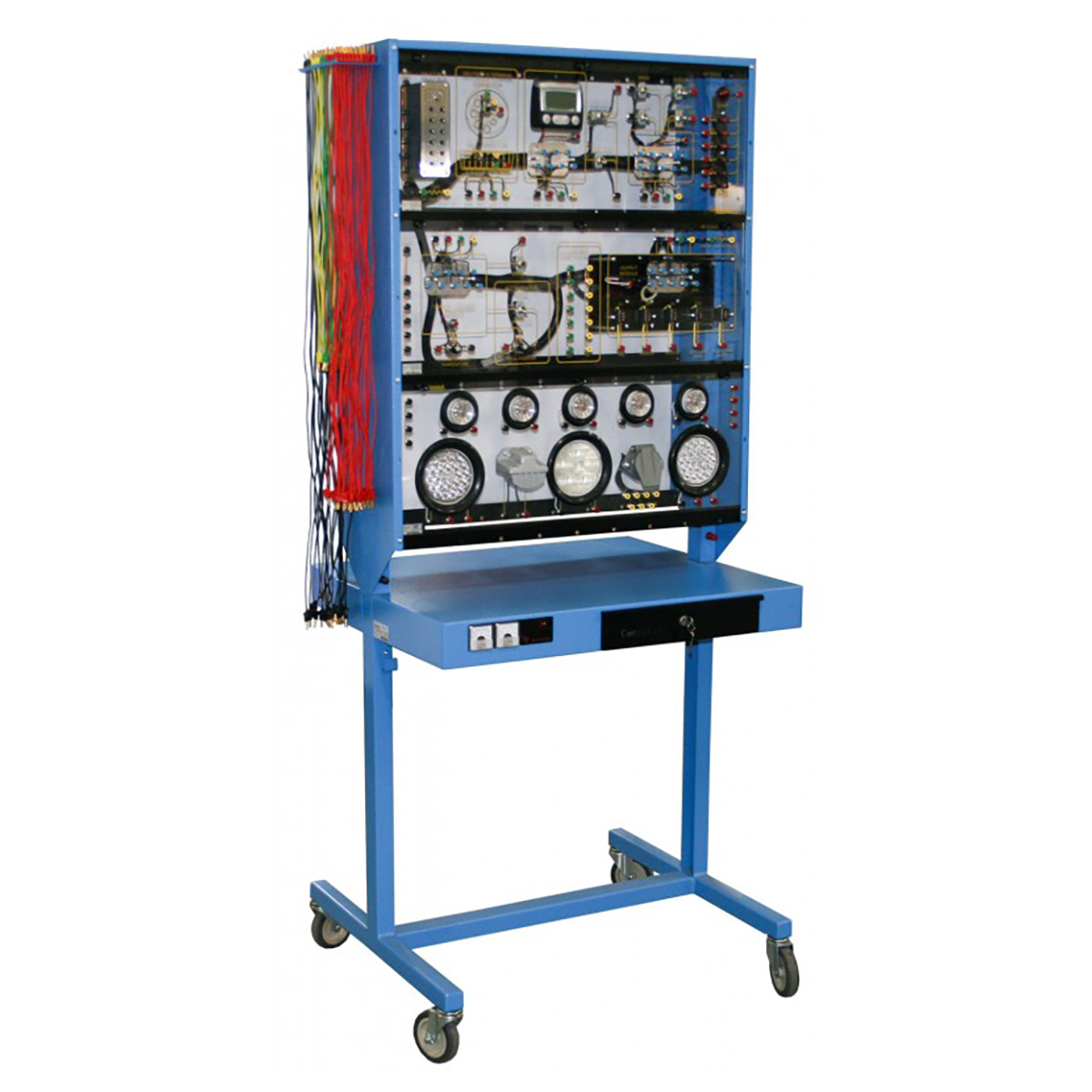
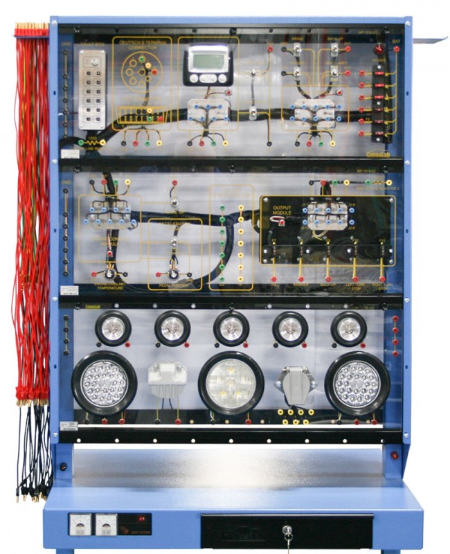
CAN Bus Multiplex Trainer
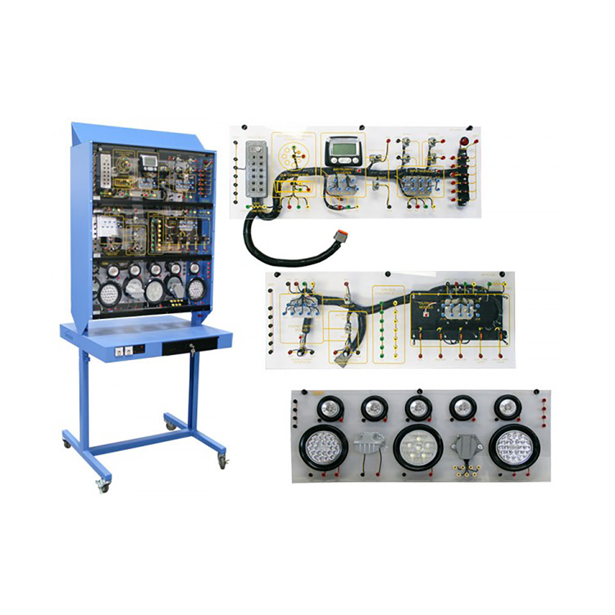
The MP-1918-1S is a single-sided CAN Bus Multiplex trainer that communicates in J-1939 protocol. Digital and analog inputs and outputs can be activated. Analog signals can be displayed using the J-1939 display. The trainer utilizes the “Moduponent®” design feature which allows unlimited expansion capabilities. This unit is equipped with an integrated electronic fault box containing 12 faults.
EDUCATIONAL ADVANTAGES:
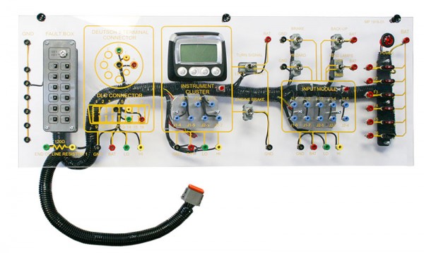
- The MP-1918-1S Trainer uses SAE J1939 communications protocol to operate a 4 module CAN Bus network , which includes both a DLC and a Deutch Connector;
- The trainer demonstrates common multiplexing circuit controls via a high speed CAN Bus network;
- Students connect modules and components using included jumper wires;
- The MP-1918-1S can be used as a CAN Bus demonstration trainer, or, using the included comprehensive student lab manual, as a CAN Bus training course;
- Built in electronic fault box allows fault insertion into circuits for diagnostic training and student comprehension;
- CAN Bus diagnostics can be taught using a DMM and DSO to look at Bus resistance, wake up signal and high speed information packets;
- Diagnostic strategies learned on the MP-1918-1S are easily transferred to a vehicle.
MAIN FEATURES
- Included user manual with theory explanations of CAN Bus, student exercises, schematics, sample scope patterns and check tests.
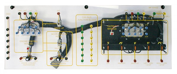
- Includes four (4) modules that replicate heavy vehicle applications including (instrument cluster, input, engine and output modules). Trainer can also be used to instruct basics of CAN Bus automotive.
- Includes digital and analog inputs/outputs.
- Each module has test points for individual diagnosis and testing.
- J-1939 display on Moduponent panel for observation of real time circuit changes.
- Sturdy powder coated metal stand equipped with lockable storage drawers and a UL approved 120VAC/12VDC power supply (w/analog voltmeter and ammeter).
- Jumper wire storage racks mounted to frame.
- Stand has two fixed and two lockable casters for easy trainer movement.
Equipment
-
MODUPONENT MP-1918-01 MASTER PANEL (TOP)
-
MODUPONENT MP-1918-02 CAN Bus PANEL (MIDDLE)
-
MODUPONENT MP-1918-03 REAR LIGHTS PANEL (BOTTOM)
Specifications
THE MP-1918-1 CAN BUS MULTIPLEX-SYSTEM TRAINER IS NOW AVAILABLE WITH ELECTUDE COURSEWARE (SOLD SEPARATELY).The CAN bus Multiplex Trainer consists of a practical set-up and the associated E-learning.
The Trainer has a completely functioning CAN bus network consisting of four control modules, which communicate via the J-1939 protocol. The CAN bus components are connected to each other using the associated wiring set. By operating switches and sensors, analogue signals are converted to (digital) serial communication. Via measuring connections, both analog and digital signals can be measured with a multimeter or oscilloscope. In addition, sensor values can be read via the informa- tion display. The Trainer has a fault box with 12 faults and a CAN bus controlled lighting system. This makes the Trainer extremely suitable for teaching CAN bus networks, CAN bus communication, CAN bus diagnosis and CAN bus lighting systems.
Through the preparatory theory and practical assignments, the participant learns :
Includes 15 learning modules for a total of 17 hours of instruction.