Hydraulic Steering & Hydrostatic Transmission with Troubleshooting
SKU: FP-MF300-VCLS-TS
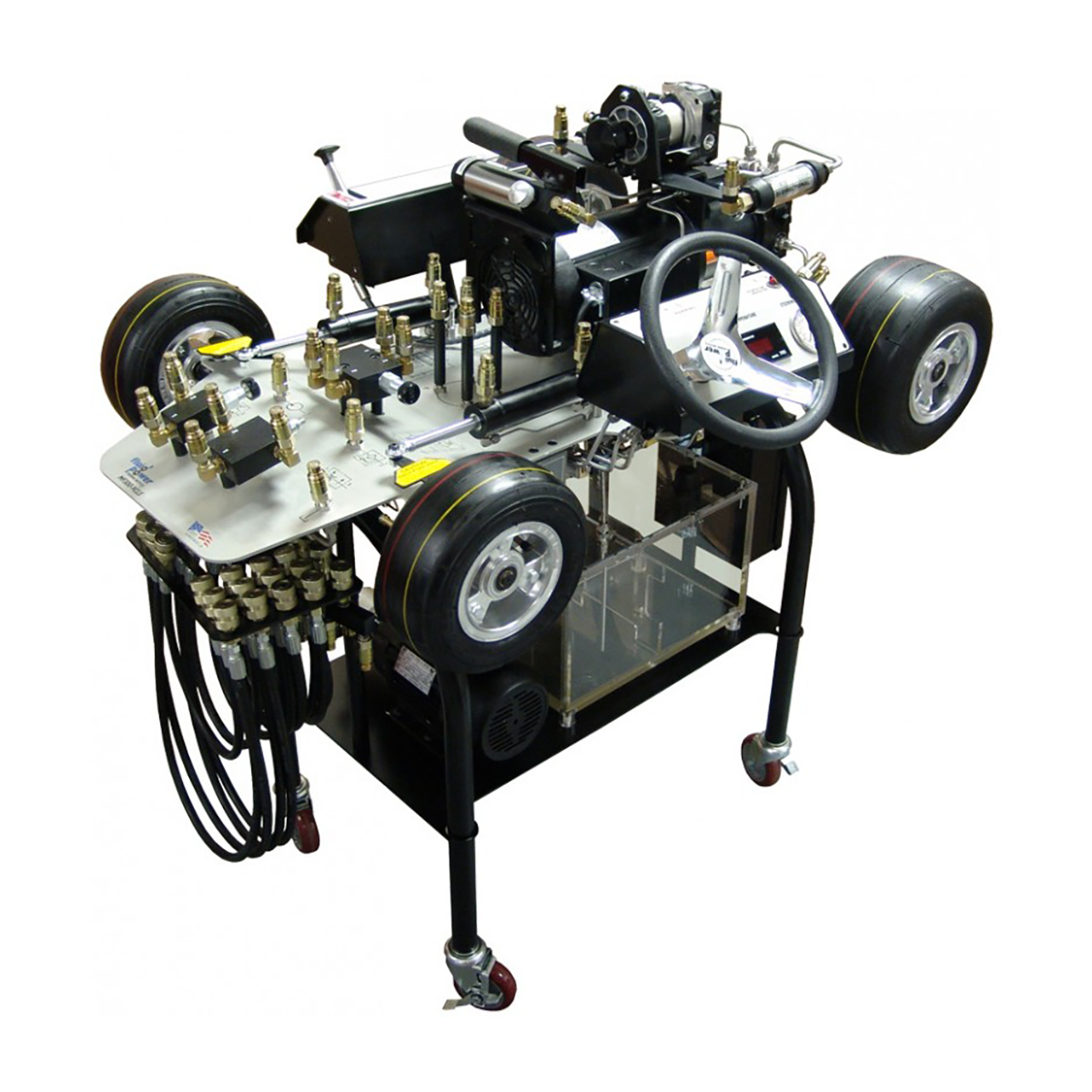
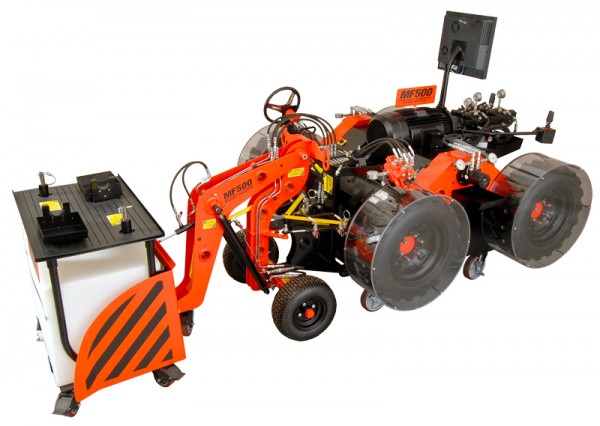
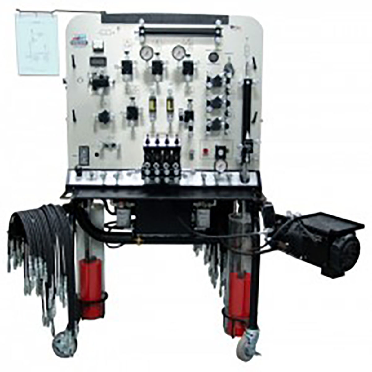
The FP-MF300-VCLS-TS simulator is designed to help schools and colleges safely and effectively troubleshooting industrial and mobile hydraulic systems.
Designed to have students understanding every component found in a typical articulated vehicle’s steering, including dual steering cylinders
Designed to have students learning the hydrostatic transmission or closed-loop system
Designed to help schools and colleges overcome the critical shortage of highly-skilled hydraulic diagnostic technicians
Will aid an instructor in teaching students how to troubleshoot the following hydraulic steering system components:
○ Fixed displacement pump
○ Steering orbitrol valves
○ Priority flow dividers
○ Steering system’s main pressure relief valves
○ Dual cross-port relief valves
○ Single and dual steering cylinders
Will aid an instructor in teaching students how to troubleshoot the following hydrostatic transmission system components:
○ Transmission doesn’t operate in either direction – forward or reverse
○ Neutral is difficult or impossible to find
○ Transmission is overheating and lacks power
○ Transmission is sluggish
System teaches:
How a priority flow divider functions (bypass-type, pressure-compensated flow control)
How a steering orbitrol valve functions
How a steering system’s main pressure relief valve functions
How to set the steering system’s main pressure relief valve
How a dual cross-port relief valve functions
How to set dual cross port relief valves
How steering cylinders function
How to interpret symbols for the components in a typical hydraulic steering system
How to read the schematic for a typical hydraulic steering system
How to properly construct a typical steering system and make all the necessary pressure settings
How a steering pump with integral pressure relief and priority flow control functions
How dual, single-rod, double-acting steering cylinders function
Dual, cross-port relief valves with mono-block body
Safety relief valve
0-1000 PSI (0-69 bar) pressure gauge
Digital temperature gauge
Spin on/off filter with by-pass indicator
Transparent reservoir with isolator mountings
All-steel frame with powder-coat finish
Four (4) wheel casters with brakes
System teaches:
Understand advantages and disadvantages of hydrostatic drives
Learn typical applications for hydrostatic drives – industrial and mobile
How to interpret the hydraulic symbols for components in a typical hydrostatic transmission
How to read the hydraulic schematic for a typical hydrostatic transmission
Learn safety practices for operating, servicing, repairing, maintaining and troubleshooting hydrostatic transmissions
How a variable displacement, over-center pump works
Understand how work pump displacement controllers – manual, manual over hydraulic, and electronic over hydraulic
Learn proper external drain pump and motor pre-start-up and post start-up procedures
Learn the function and purpose of a charge pump
Learn the function and purpose of a charge pressure relief valve
How to properly set a charge pressure relief valve
Learn the function and purpose of the dual charge check valves
How to operate a typical hydrostatic transmission for:
System start-up
Charge circuit – neutral
Charge circuit – forward and reverse
Forward operation
Reverse operation
Low pressure loop operation
Dynamic braking
Case drain circuit
Cooling and filtering circuit
High-pressure relief valve operation
Learn proper and safe towing procedures for vehicles equipped with hydrostatic wheel drive systems
Understand the advantages and disadvantages of dual, parallel motors
Understand the advantages and disadvantages of dual, series motors
How the “dynamic braking” in a hydrostatic drive functions
How to construct a dual-parallel drive circuit
How to construct a dual-series drive circuit
Learn common pitfalls which lead to start-up failures on hydrostatic transmissions
Learn common pitfalls which lead to premature failure of hydrostatic transmissions
How to troubleshoot the following hydrostatic transmission system components:
Transmission doesn’t operate in either direction – forward or reverse
Neutral is difficult or impossible to find
Transmission is overheating and lacks power
Transmission is sluggish
Components Include:
1.5 HP electric motor: 115V single-phase, C-frame, 1750 RPM
Variable-displacement, over-center, axial-piston pump with manual operator
Cut-away of identical pump, which operates in tandem with the drive pump (allows students to study how an over-center pump works while it is operating)